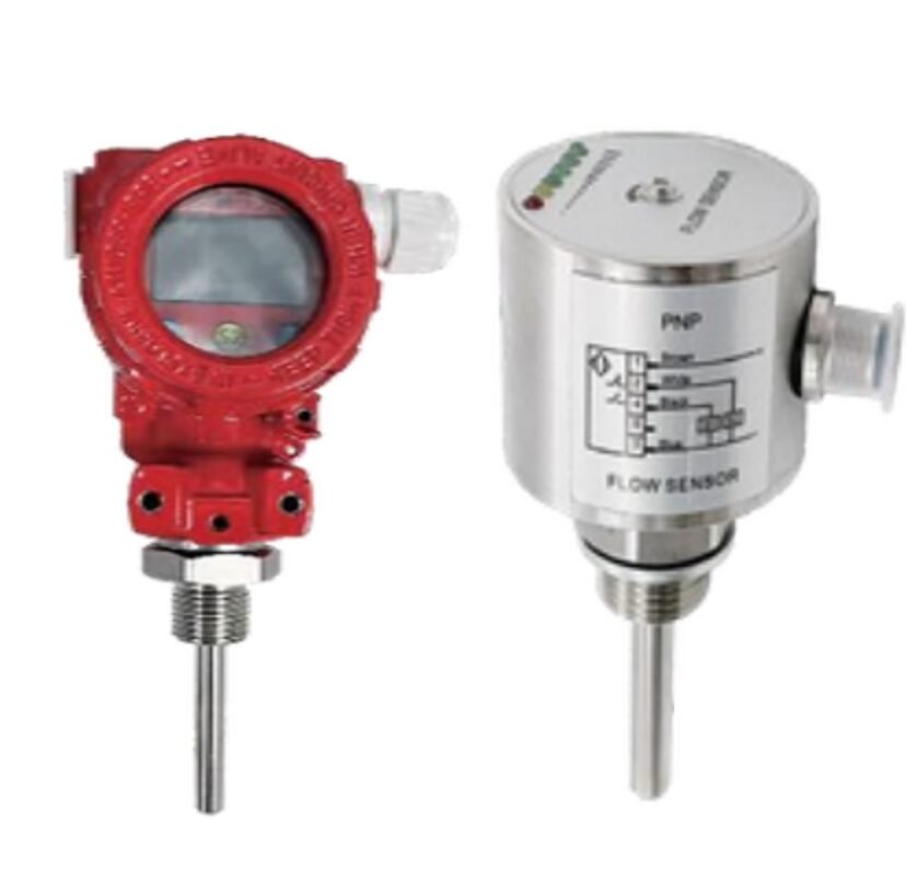
The VMAL Flow Switch is a mechanical flow monitoring and control instrument designed to detect whether the flow of water, gas, or oil is above or below a preset threshold. When the measured flow reaches the configured set point, the switch generates a control signal that can be used by other equipment in the system, such as pumps, valves, alarms, or control circuits.
According to the catalog, the flow switch range supports different sensor lengths, process connections, power supplies, and output configurations. Depending on the selected version, available outputs include PNP, NPN, relay, and 4–20 mA, while the protection level is IP67.
VMAL Flow Switch for Automatic Flow Monitoring
A flow switch is used when a system needs to know whether fluid is actually flowing at the required level. Rather than continuously displaying flow like a conventional flow meter, a flow switch can respond when the flow reaches a defined switching point.
The VMAL Flow Switch works by detecting the flow condition of the medium inside the pipe. When the flow reaches or exceeds the preset threshold, the instrument generates an electrical signal or switching action. This signal can then be used to control another device or trigger a system response.
The catalog describes applications including air conditioning, water treatment systems, water cooling equipment, liquid delivery systems, pump systems, and industrial process control. It also identifies applications in industries such as HVAC, pharmaceutical, food and chemical processing, water treatment, power, petroleum, and industrial production.
For ValveLink Europe customers, this makes the VMAL Flow Switch a practical option where flow presence or flow level needs to be monitored and converted into an automatic control signal.
Flow Switch Working Principle
The operating principle is based on detecting the force or pressure change produced when a fluid moves through the sensing element. When the flow reaches the configured threshold, the instrument changes its output state.
The switching point can be adjusted according to the instrument configuration. The catalog specifies a potentiometer setting for the standard flow switch versions, while other versions use button settings and a seven-segment LED digital display.
The standard flow switch versions provide an LED indication of flow rate and continuously adjustable switching quantity. The catalog also highlights that the design has no moving parts, requires no maintenance, and causes almost no overall pressure loss.
This operating concept allows the flow switch to be integrated into automatic systems. For example, the output can be connected to a pump control circuit or another control device so that the system can respond when the detected flow is outside the configured switching condition.
VMAL Flow Switch Technical Specifications
The VMAL Flow Switch is designed for monitoring different flowing media. The catalog specifies the following measuring ranges:
| Parameter | Specification |
|---|---|
| Water flow range | 3–300 cm/s |
| Gas flow range | 200–3000 cm/s |
| Oil flow range | 3–300 cm/s |
| Switch accuracy | ±1 to ±10 cm/s |
| Warm-up time | 3 minutes after power-on |
| Working pressure | <100 bar |
| Medium temperature | -20°C to 80°C |
| Process connection | G1/2, G1/4 and M18 internal thread connections |
| Output signal | PNP / NPN / Relay |
| Power supply | 24 VDC, 85–265 VAC, 120–370 VDC |
| Sensor length | 15, 20, 30, 40, 50, 60 mm; customizable |
| Setting method | Potentiometer setting |
| Response time | 2–10 s |
| Output load | Current: 250 mA; Relay: 30 VDC/5 A, 220 VAC/5 A |
| Protection | IP67 |
| Wiring | M12 connector |
These specifications represent the standard flow switch configurations shown in the catalog. Other versions in the same product range add 4–20 mA output, digital display, or multiple relay outputs, so the exact specification should be checked against the selected configuration before ordering.
The catalog also specifies protection against reverse polarity, overload, and short circuit and identifies the connection as an M12 connector.
Sensor, Materials and Output Options
The VMAL Flow Switch is available with different sensor and body configurations depending on the version. The catalog specifies ANSI316L for the probe, while the body is shown as either ANSI316L or PVC depending on the configuration.
Several process connection options are available, including:
- G1/2 external thread
- G1/4 external thread
- M18 × 1.5 internal thread
- Custom-made process connections where specified in the catalog
The available sensor lengths include 15 mm, 20 mm, 30 mm, 40 mm, 50 mm, and 60 mm, with custom lengths available depending on configuration.
Output selection is another important consideration. The catalog provides configurations with PNP output, NPN output, one relay output, and versions with 4–20 mA output. The digital versions can also provide 1/2/3/4 relay outputs depending on configuration.
The integrated flow and temperature version additionally provides 4–20 mA, PNP, NPN, or relay output, with button settings.
Flow Switch Features and Installation
The VMAL Flow Switch is designed with several features intended to simplify installation and operation. The catalog highlights IP67 protection, no moving parts, no maintenance requirement, continuously adjustable switching quantity, multiple available sensor probe lengths, and almost no overall pressure loss. It also states that one version can be applied to multiple pipe diameter requirements.
Installation should follow the direction and arrangement shown in the catalog. In particular, the installation notes state that the flow switch should be installed in the opposite direction of the water flow. Where sediment exists in the pipe, the catalog provides a specific installation arrangement that should be followed.
The catalog also specifies a recommended distance between the installation point and an elbow:
A ≥ 3D
where:
- A = distance between the installation point and the elbow
- D = pipe diameter
This spacing should be considered during installation because the catalog specifically provides it as part of the installation guidance.
The flow switch can be installed in configurations shown as horizontal installation, side mount, and curve installation, depending on the piping arrangement and the installation diagram for the selected version.
Applications of VMAL Flow Switch
The VMAL Flow Switch can be used wherever a system needs to detect and respond to changes in fluid flow. The catalog identifies applications in industrial boiler systems, water plants, wastewater treatment, power industry, petrochemical applications, and medical devices.
Typical application areas described in the catalog include:
- HVAC and air-conditioning systems
- Water treatment
- Water cooling equipment
- Liquid delivery systems
- Pump systems
- Industrial process control
- Industrial boiler and water plant systems
- Wastewater treatment
- Power industry
- Petrochemical processes
- Pharmaceutical and food processing
In a pump system, for example, the flow switch can detect whether the required flow condition is present and send a signal to the control circuit. The catalog describes flow switches as devices that can monitor fluid flow and trigger alarms, open or close valves, and adjust pump station operation.
For cooling and water-treatment applications, the instrument can similarly be used as part of an automatic protection or control system where flow status needs to be detected.
Selecting the Right VMAL Flow Switch from ValveLink Europe
Choosing the correct VMAL Flow Switch requires checking the fluid, flow range, pipe connection, sensor length, power supply, output signal, operating pressure, and medium temperature.
For water applications, the catalog specifies a measuring range of 3–300 cm/s; for gas, 200–3000 cm/s; and for oil, 3–300 cm/s. The specified medium temperature range is -20°C to 80°C, while working pressure is below 100 bar.
The required electrical output should also be selected according to the control system. Options include PNP, NPN, relay, and 4–20 mA, while power supply options include 24 VDC, 85–265 VAC, and 120–370 VDC depending on the selected configuration.
ValveLink Europe can help customers identify the appropriate configuration based on the actual piping and control requirements. When requesting a quotation, it is useful to provide the flowing medium, expected flow range, pipe size, process connection, required sensor length, power supply, output signal, operating pressure, and operating temperature.
Contact ValveLink Europe for the VMAL Flow Switch and provide your application requirements so the suitable configuration can be checked against the catalog specifications before ordering.